Thermal Balancing Valve Schematic

Piping Diagram For Body Sprays Basic Master Shower Shower Plumbing Body Spray

Benefits Of Installing Balancing Valves On The Return Side Of Coils Hays Fluid Controls Bloghays Fluid Controls Blog

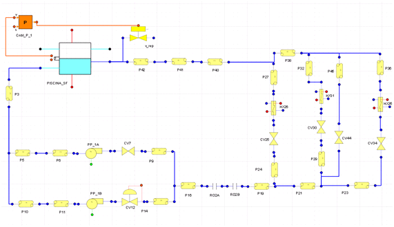
Basic Diagram Of How A Swimming Pool Plumbing System Works Pool Pumps And Filters Swimming Pool Plumbing Swimming Pools
How Does A Differential Pressure Bypass Valve Work Caleffi

Variable Voltage Power Supply From Fixed Voltage Regulator Circuit Diagram Voltage Regulator Electronic Circuit Design

Thermal Balancing Valve And System Using The Same Diagram Schematic And Image 06
Matches perfectly with variable speed recirculation pumps for effi cient energy usage.
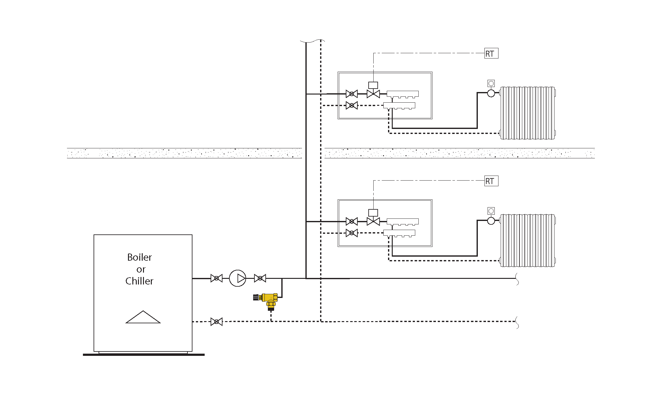
Thermal balancing valve schematic.

Modeling A Circuit Setter Balancing Valve Engineered Software Knowledge Base

Plumbing Topic Domestic Water Recirculation Systems Part 7
Title

Ghim Của Cuhiệp Phan Tren Cong Nghệ Trong 2020 Cong Nghệ

Recirculation Kit

Discrete Class Ab Transistor Audio Power Amplifier Circuit Diagram This Is A Class Ab Transistor In 2020 Circuit Diagram Power Amplifiers Electronic Circuit Projects
Presure And Mass Flow Balance In Hydraulic Liquid Systems Pipeliq

Mixing Valve An Overview Sciencedirect Topics
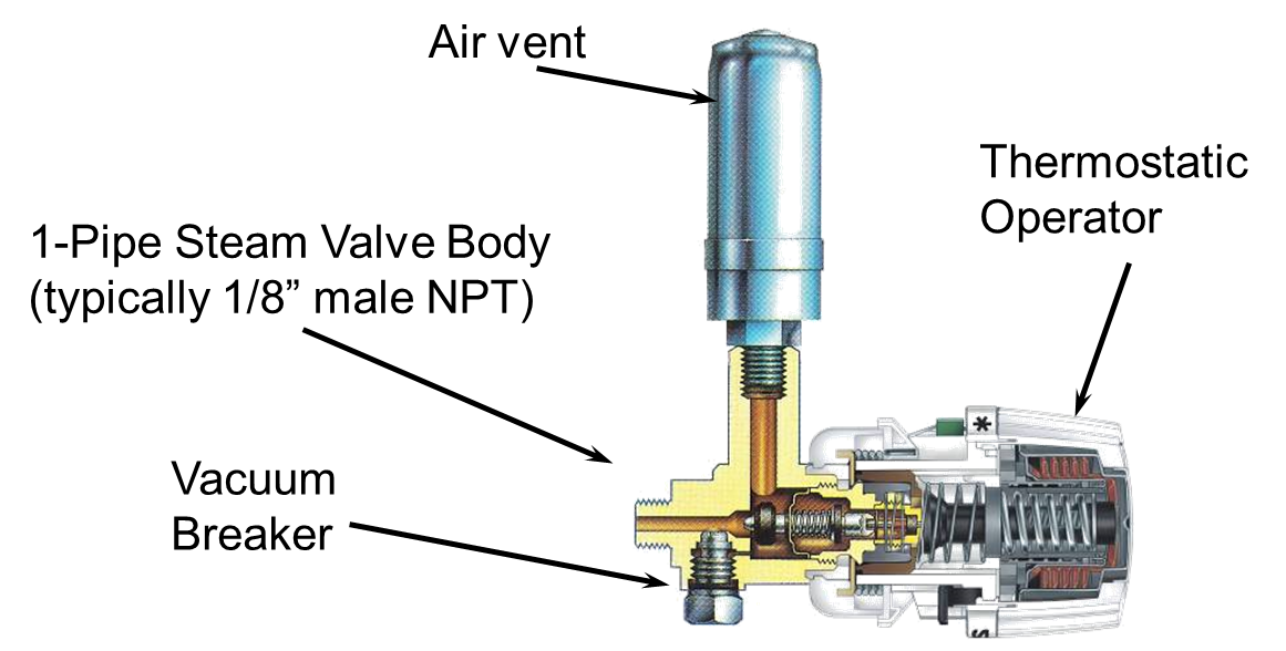
Thermostatic Radiator Valves On Steam Heating Systems Building America Solution Center

Pin On Subwoofer
Title

Bradley 2010 Navigator Thermostatic Mixing Valves

What You Need To Know About Residential Steam Boilers Steam Boiler Boiler Boiler Repair
Power Plant Thermal Balance Simulation Toolkit Thermal Balance

Pneumatic Circuit Symbols Explained Symbols Electronic Schematics Valve

In A Coordinated Electrical Distribution System Only The Device Nearest To The Fault Will Trip Unless The Coordinated P Basic Principles Electrical Substation

Termohygrometer

Check Valves Spirax Sarco
Https Encrypted Tbn0 Gstatic Com Images Q Tbn 3aand9gcqjxxdperzmpozbveh02j1wutkfs2v08p Onnpmsh5bx3 Hzs6 Usqp Cau

Daikin Air Conditioning System Building Hvac Diagram

Piping For Radiant Panel Heating 2015 05 11 Plumbing And Mechanical

Types Of Safety Valve Spirax Sarco

Basic Instrument Symbols Bmp 536 687 Piping And Instrumentation Diagram Chemical Engineering Process Engineering

An Installer S Guide To Wet Underfloor Heating Manifolds Ambiente
Source : pinterest.com
